On Sept.18, 2003 the finish kit was ordered, along with a TMX IOF-360 from Mattituck!!
I rented a U-Haul and drove to Van's on Dec. 1, 2003. Diane and I loaded the finish kit up and drove it home! This page will show the progress of the last of the 4 kits ....
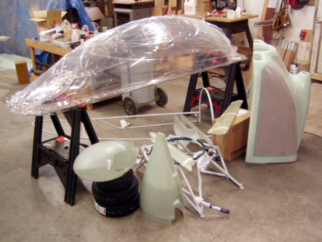
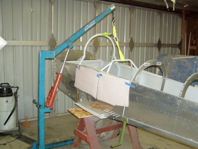
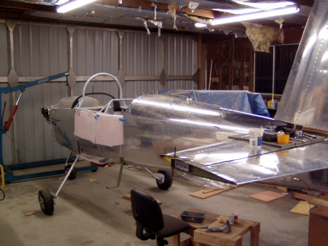
First flare! Elevating the airframe in preparation for mounting the gear.
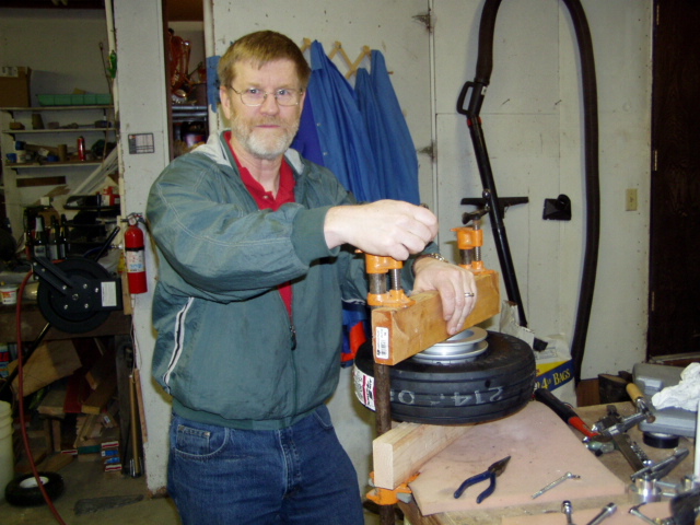
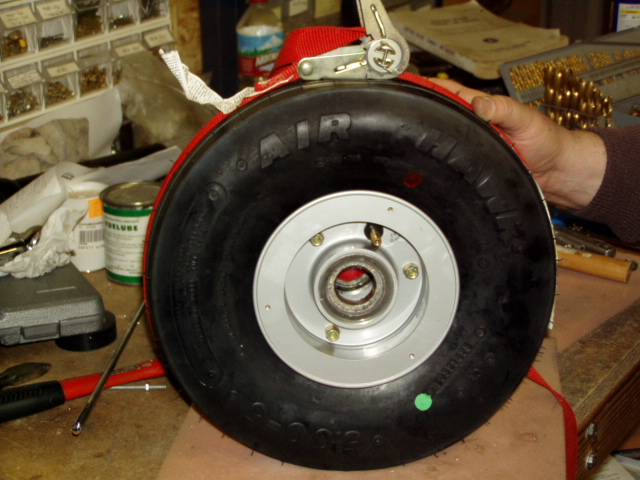
Gently compressing wheel halves together.
A closeup of our high-tech wheel assembly operation.
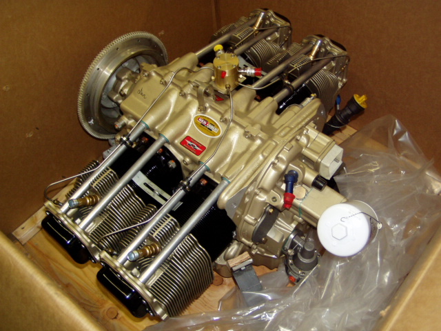
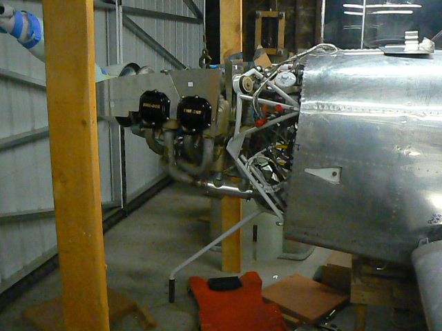
Isn't this the prettiest engine you've ever seen?
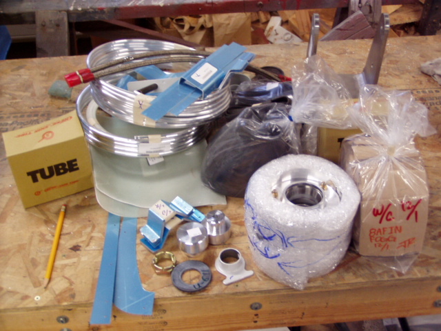
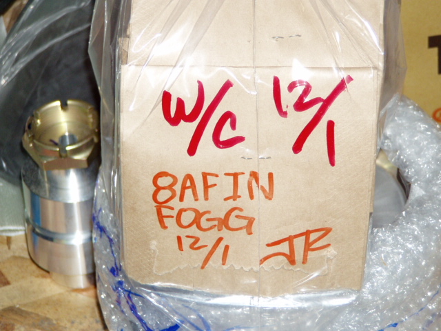
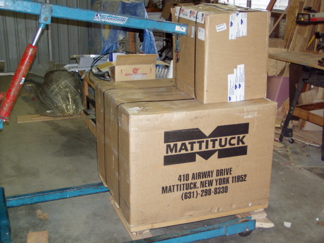
Aren't these the finest looking boxes you have ever seen?
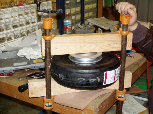
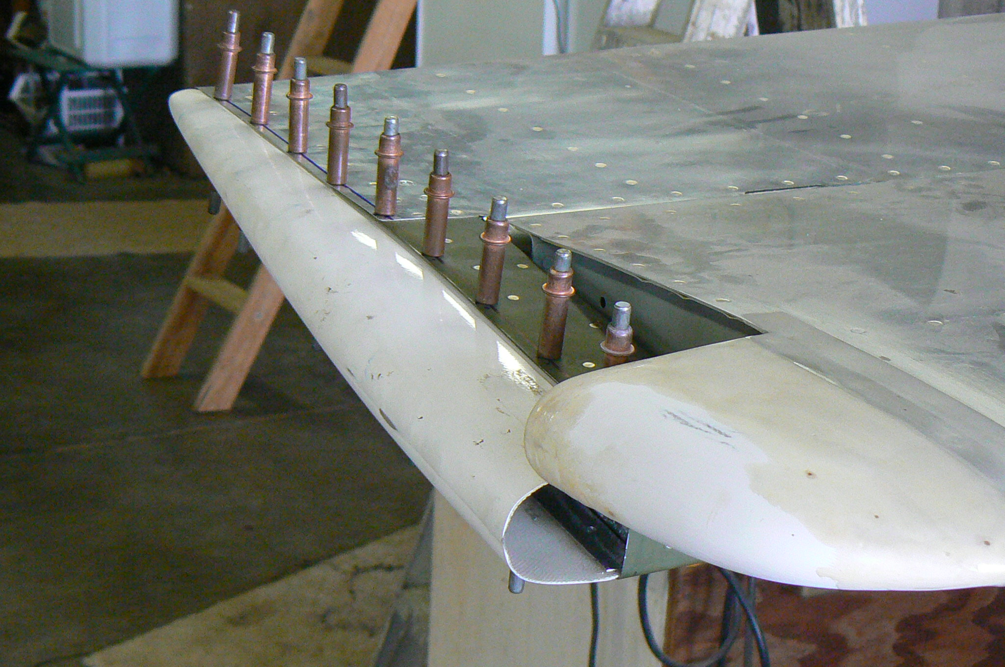
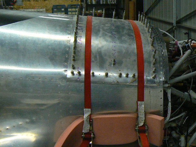
The idea here was that the strap clamp would encourage the tire to expand against the wheel flanges.
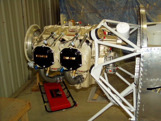
The engine ... where it belongs.
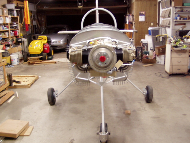
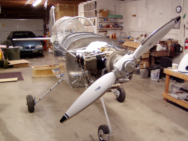
Looking more and more like an aircraft ....
static ports hooked up
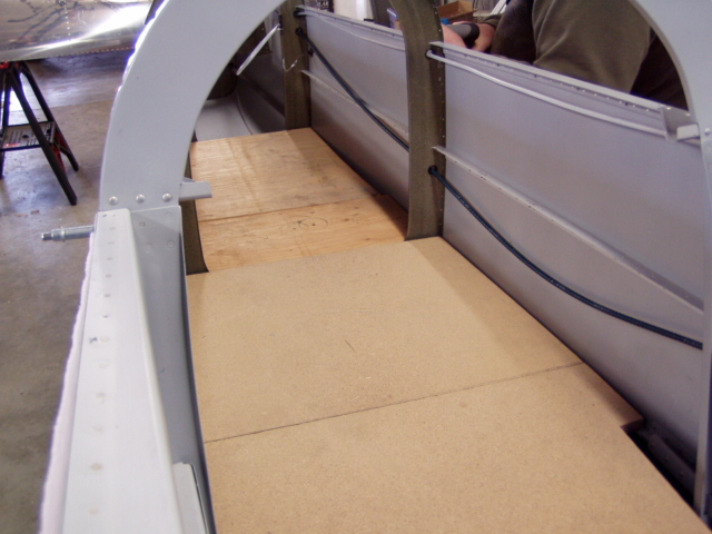
Making a bed for a 6' '2" 220 lb. bucker ....
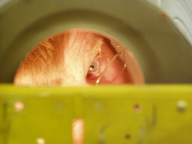
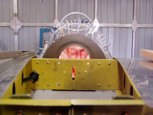
Beginning to rivet the aft skin on, and sincerely hoping I can get back out .....
Two comments:
1) It is loud in there.
2) Trouble lights get hot.
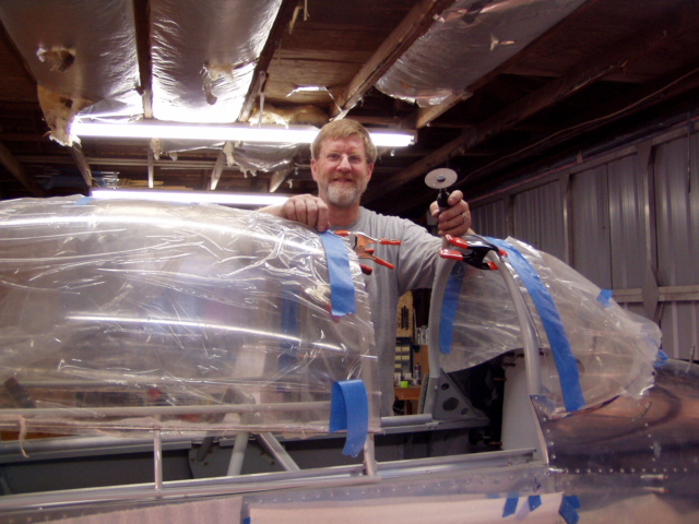
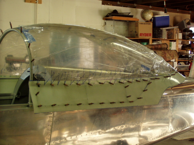
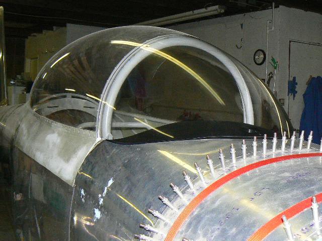
Nearly ready to add the canopy structure.
Initial trimming is done, and THE CUT is made. We decided to make this cut early in the fitting process. After stressing about it for the last 6 1/2 years, it was basically a non-event.
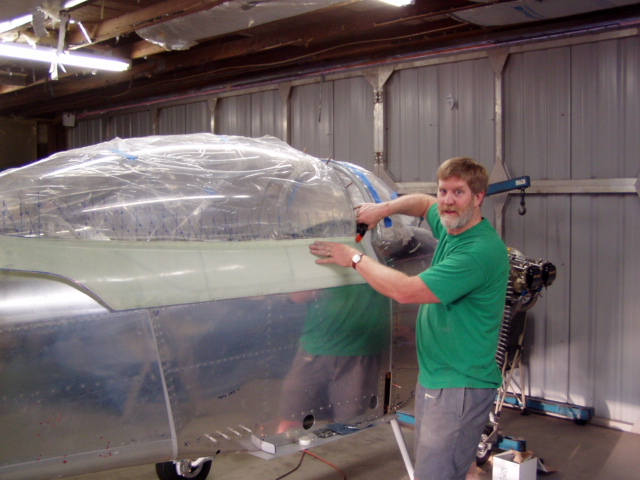
Ready to make the final trim cuts. It is July and the weather is warm here in Oregon, making for a somewhat uncomfortable shop but a happy canopy.
First test fit of the canopy skirt.
All holes through the canopy into the frame are drilled. Fitting the skirt requires that we drill holes in the skirt that will match the existing holes in the canopy, and the plans suggest this method for hole matching ... draw intersecting lines on the canopy that meet at the hole, then redraw those lines once the skirt is clamped and taped in place.
We'll see how it goes ...
The skirt is fully drilled to the canopy frame. Matching the existing holes worked reasonably well, and the good news is that those holes that, uh, missed badly will get covered up by fiberglass.
Fiberglass tip on horizontal stab drilled on and beginning to fit a balsa insert.
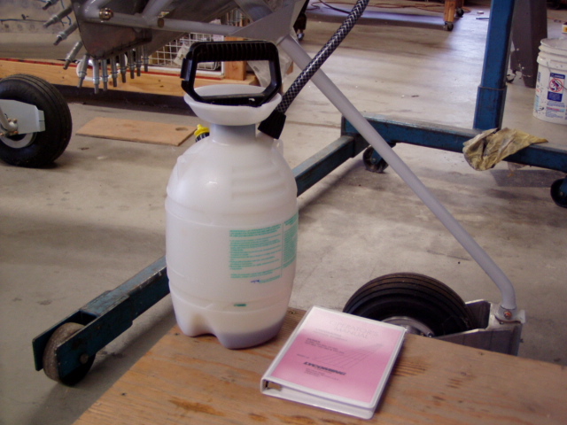
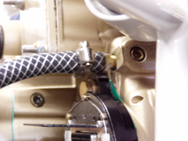
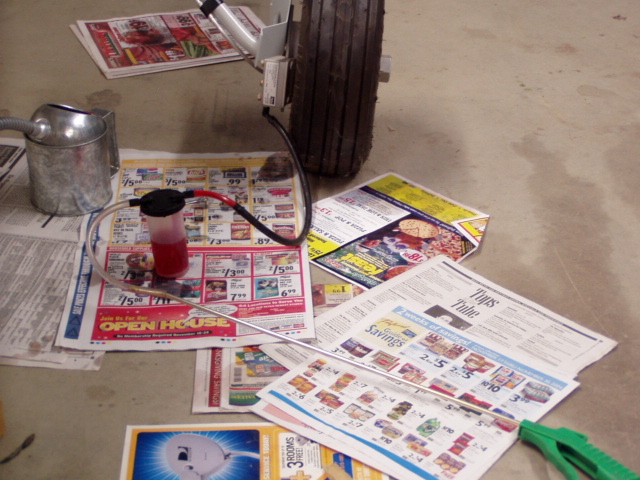
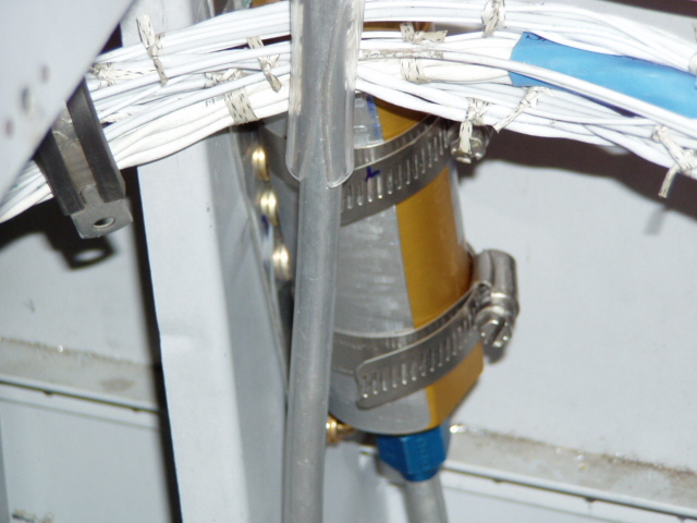
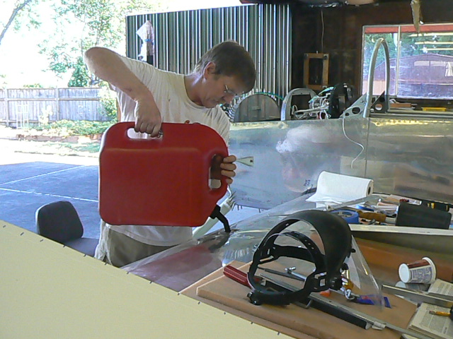
I wanted to add some more preservative oil ... my engine came pickled, but it will be a while yet before it is run. I took,some advice from neighbor and RV-4 builder Jim Clare and used an idea he got from an Orndorff video on pre-oiling an engine prior to the first run:
Using a garden sprayer, I cut the end of the hose off and attached it to a bayonet to 1/4" pipe fitting that fits nicely into the oil pressure sender location. Pumping up the sprayer pushes the fluid in nicely ... I will use this techinque with the break-in oil when we are ready to run the engine.
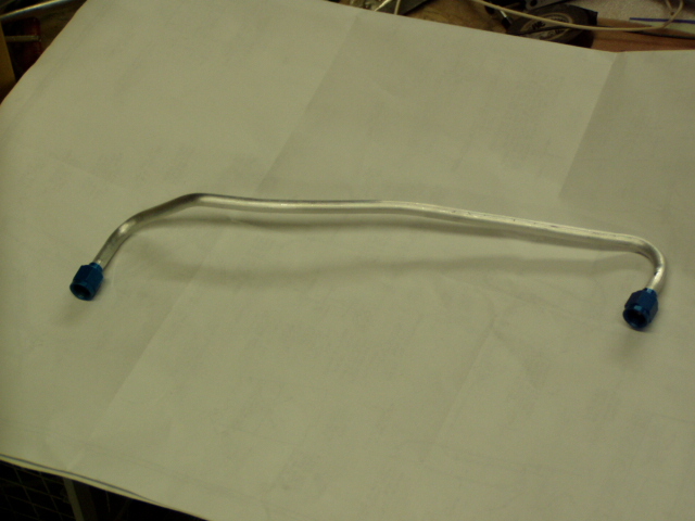
The first fuel line. It took me three tries to get one that fit. Ken Foote's presence was the key ... this one fit like a glove.
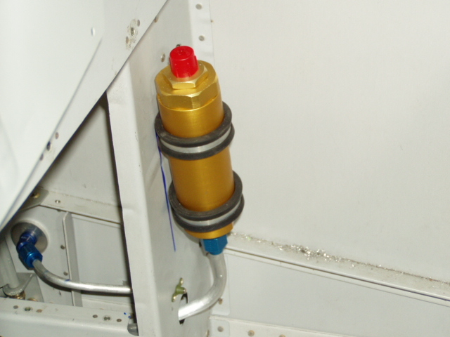
Attaching the fuel line to the fuel filter.
Fuel filter, with the left vent line visible to the left.
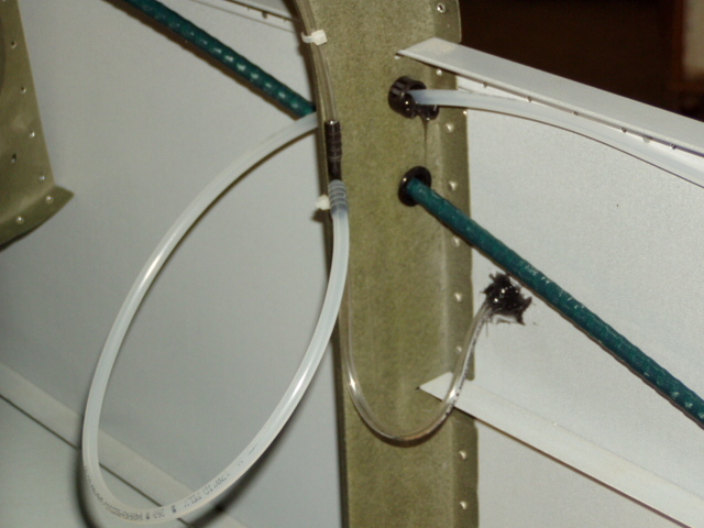
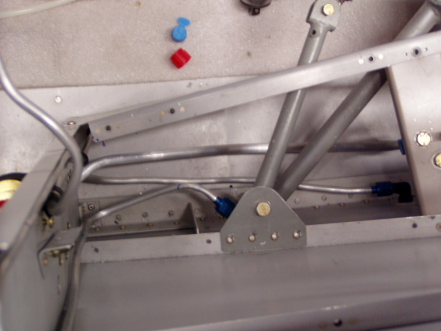
Looking down, the large line is for fuel, and the two smaller lines are the tank vent and the brake lines.
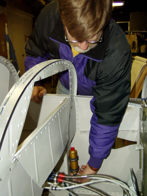
Adding hydraulic fluid into the brake lines. This technique was suggested in the plans and worked a lot better than my first attempt at filling the resevoir and trying to bleed from the bottom.
Click here to add your text.
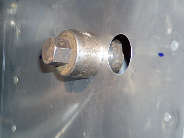
Punching holes in the firewall for the throttle and prop governor cables. This chassis punch is Ken's (although it should be mine by now as I've had it in my shop for so long) ... it did a beautiful job.
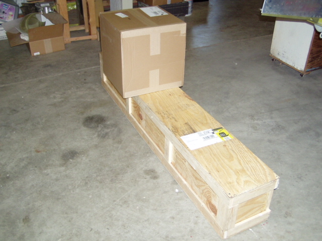
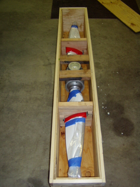
December 15, 2004 .... two nice boxes arrive from Whirlwind Propellers.
A very well packed 200RV is inside.
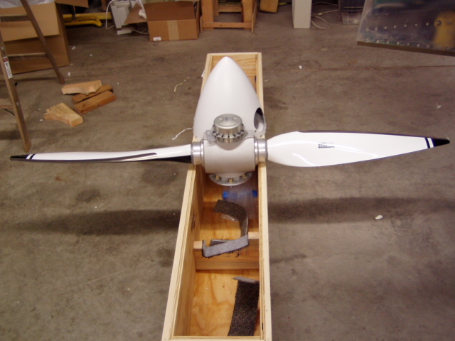
Unpacked and ready to install ...
After careful installation, it sure looks good!
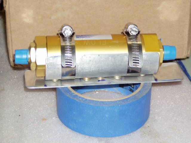
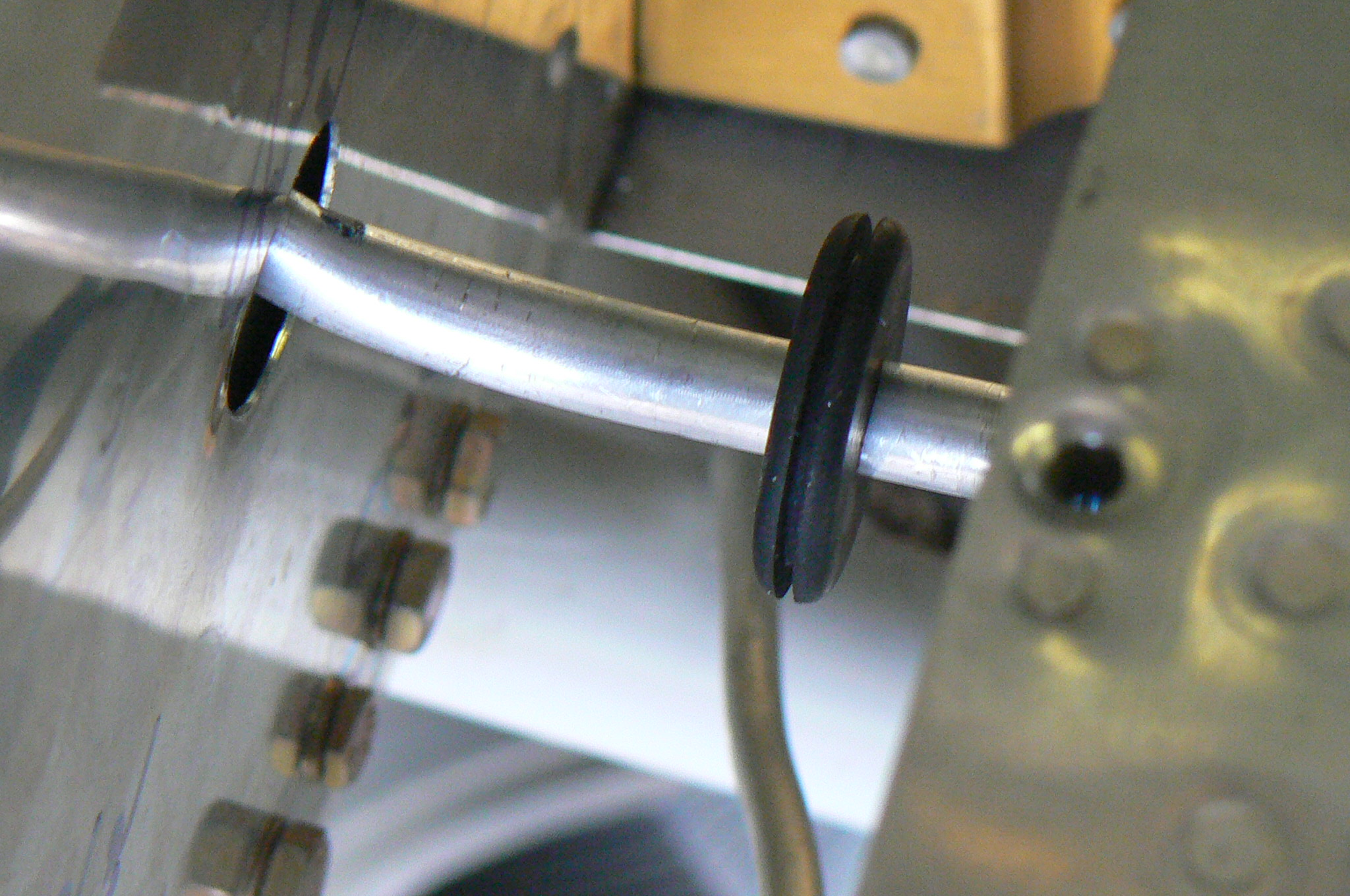
While wiring the panel, Ken and I got to talking about what a challenge it would be to remove the fuel filter (original installation here) for cleaning. Our concern was the relative difficulty in getting to the cushioned clamps. Getting them out would not be too bad, but getting them in might be a vocabulary-expanding experience. We concluded that a simple plate with a slightly raised cradle could be riveted to the bulkhead. The cradle is riveted to the mounting plate with washers in between to allow space for the hose clamps.
The resulting assembly attached to the bulkhead.
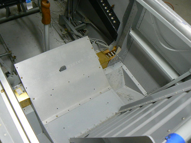
Temporary installation of seat pan prior to prepare for fitting front seat.
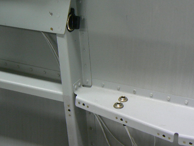
Initial placement of the headphone jacks in the rear is not going to work well, as Diane's arm wants to rest there. These will be moved to the bulkhead just below the power outlet.
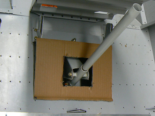
The start of a prototype for a cover in the rear. A boot will be added here as well.
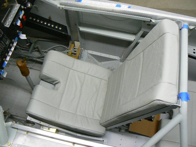
First installation of rear seat, built by Alex White of Starworks, located at Twin Oaks Airpark in Oregon.
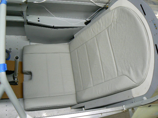
The front seat, ready for a pilot.
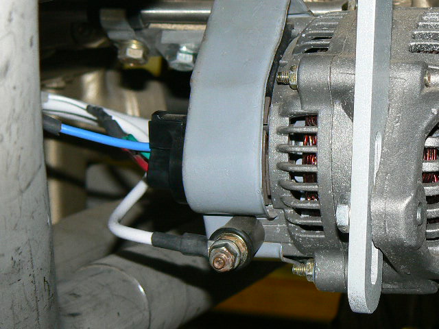
Beginning to hook up the firewall-forward electrics.
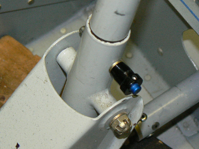
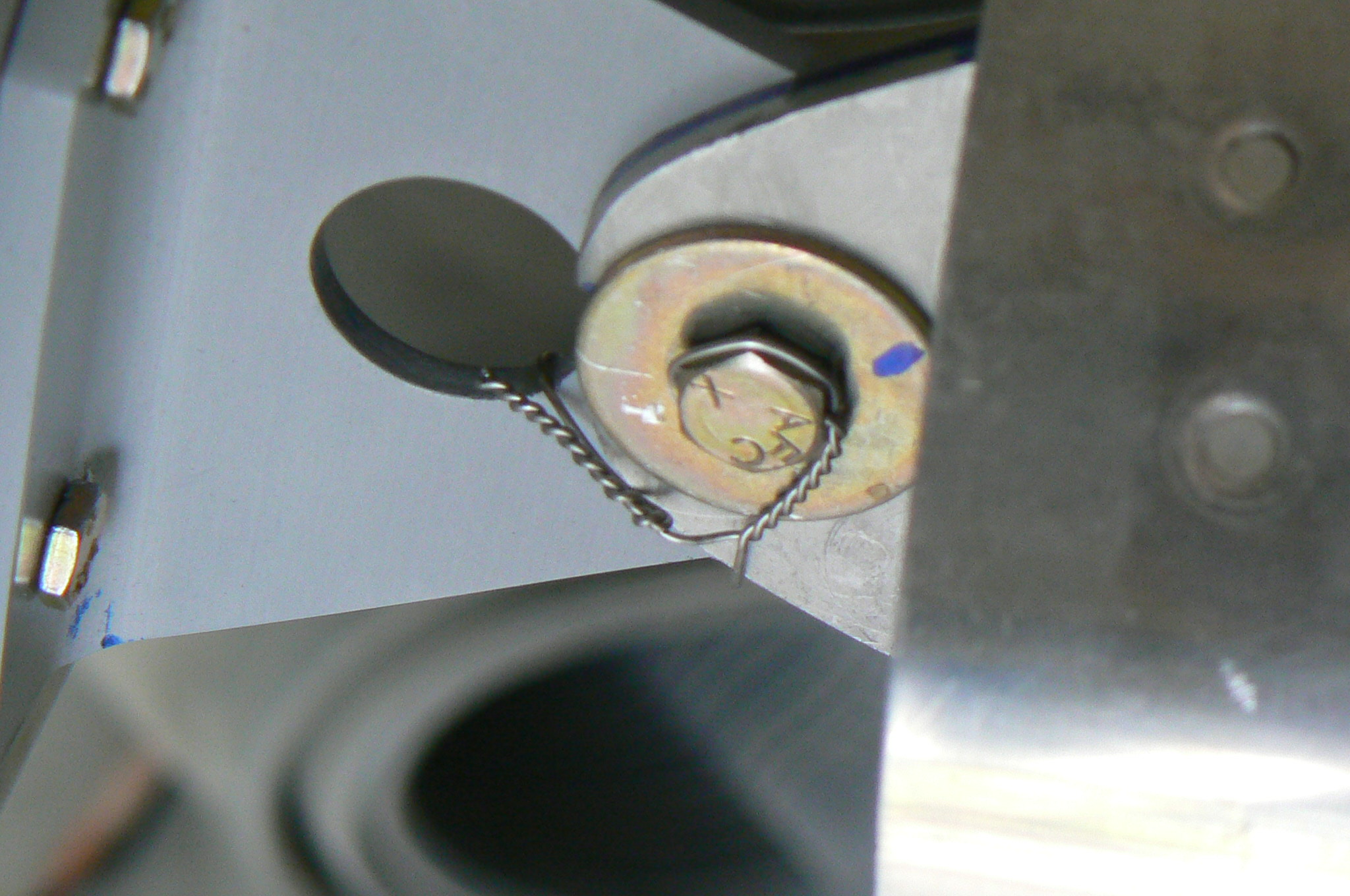
A Service bulletin suggests an AN-3 bolt here to secure the rear stick. I opted to make it a pre-flight
option to have the stick installed or not.
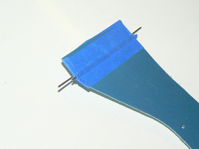
The aft wing root fairings require a joggle bend at the forward spar position. My first attempts with a hand seamer were awful. With new parts and Ken Foote's idea of using two lengths of small rod taped at each bend line and squeezing the assembly in a bench vice ...
I am a lot happier with the results!
Attached the right flap and trimmed the top inboard skin to fit against the fuselage. This will be trimmed a bit more to provide clearance ... the flap fairing will cover up the gap.
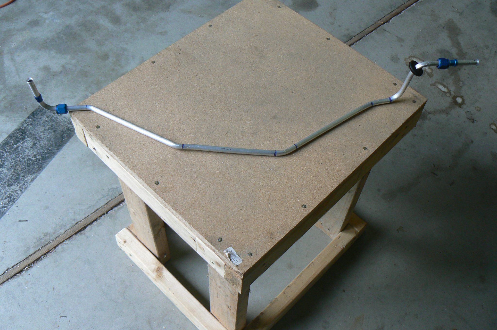
The fuel line to the left tank. This is a short piece that must make a bend immediately upon entering the fuselage.
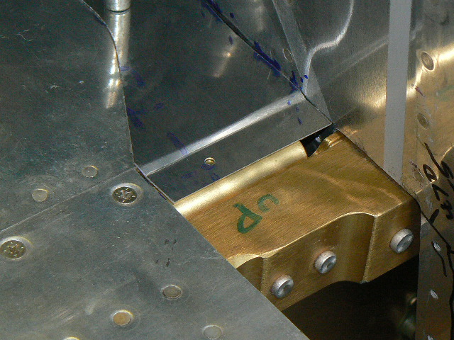
Closeup of the forward tank mount. The bracket attached to the tank (to the right in this picture) is slotted to allow the wing to tear away from the fuselage.
Attempt #3 at the fuel line from the fuel selector to the right tank. This was a challenge to get into the airframe in one piece.
3 gallons of avgas go into each tank in preparation for testing the fuel lines. With the fuel pump on and the starter not turning, it would seem that the maximum fuel pressure would be present in the lines, allowing a leak test before the fuselage top skin goes on and the great access to the fuel components inside the fuselage goes away.
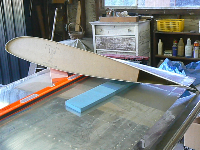
A particle board form holds the wing tip shape as they are fitted to the wings.
Drilling the tips on to the elevator.
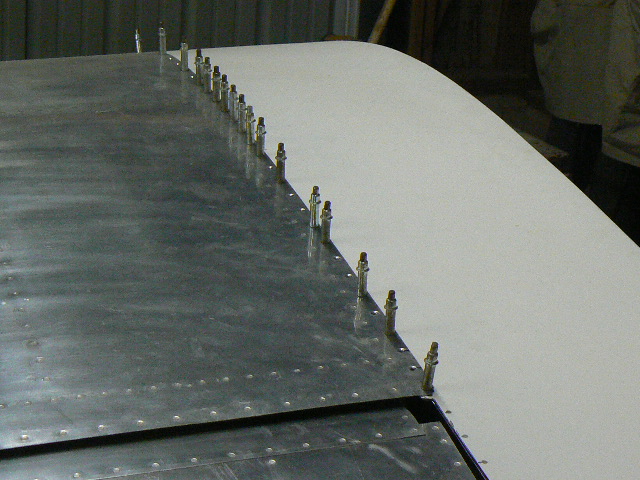
The right wingtip drilled, dimpled, and nutplates installed. It took a fair amount of fitting before the top of the wingtip lined up correctly with the top of the wing. A straight edge should rest evenly from the wing out to the edge of the wingtip.
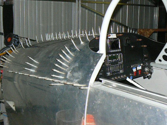
Ready to rivet the final skin on to the fuselage. It took 4 sessions to get this done because getting a bucking bar in place was often a challenge due to wiring, plumbing, instruments, and old eyes.
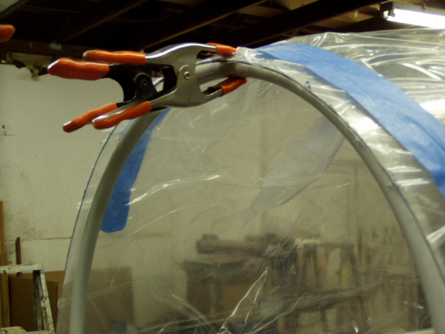
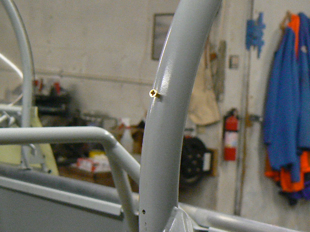
The rollbar is drilled and tapped for #6 screws in preparation for attaching the windscreen.
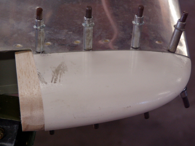
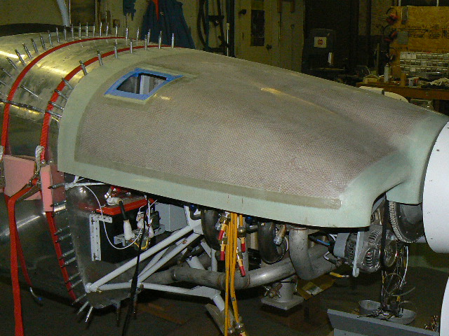
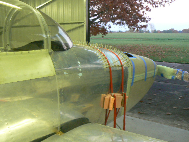
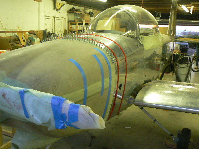
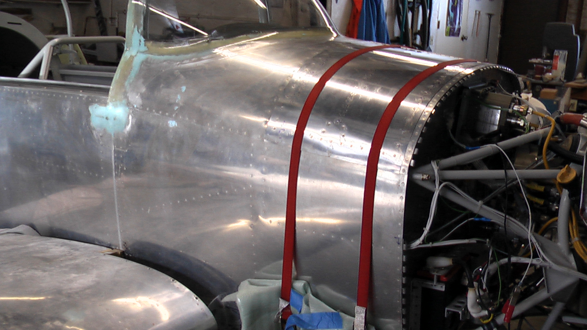
The forward baggage door is temporarily strapped in place to aid in the fitting of the top cowl.
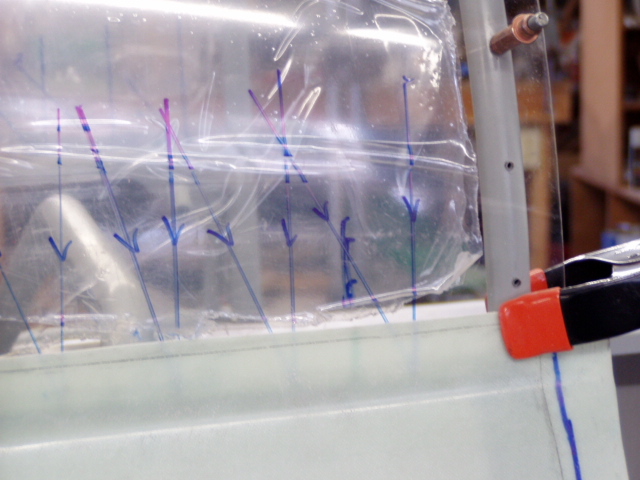
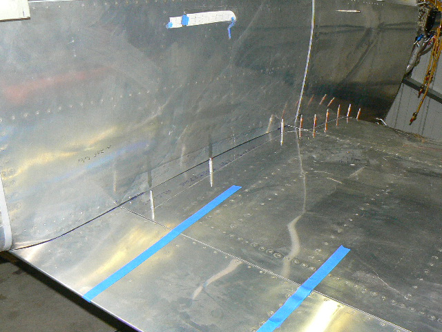
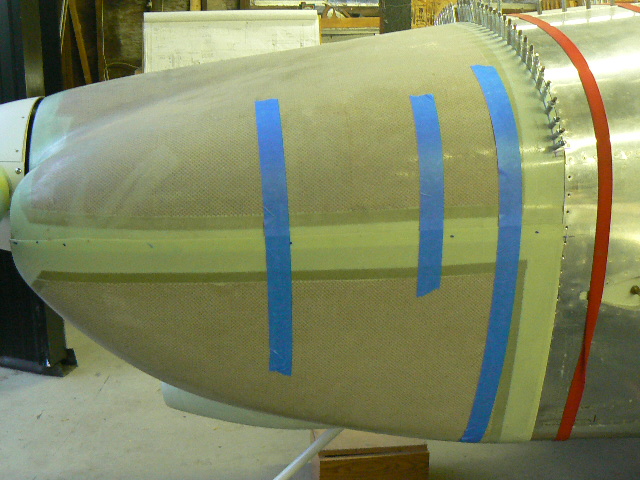
Initial fitting of the top cowl. The blue line that you can see just forward of the strap is a reference line. Two inches forward of that line is where the cowl will be trimmed.
Taking 14 deep breaths before fhe first cut is made ...
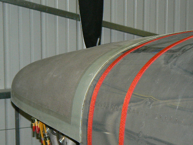
The lower cowl has been slotted for the nose gear and fitted for the first time. It will be trimmed to meet the firewall and the sides of the upper cowl.
The windshield, screwed to the rollbar and ready to be epoxied to the fuselage.
Someday we will push the airplane out and begin to convert avgas to noise ...
Patiently waiting amidst the dust of an unkempt shop, but getting closer to the first flight every day.
Hanging a trouble light inside the cowling was an aid in defining where the lower cowl needed to be trimmed to match with the upper cowl.
The side hinges are installed, but i did not leave any clearance between the cowl halves and some trimming is required, as it currently takes a lot of effort to get the hinge pin in.
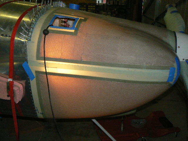
Beginnng to work on the baffling, and the nose is elevated to prepare for nosegear modifications per the recently issued service bulletin.
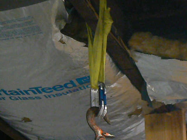
The airframe is humg from the ceiling joist, after braces were installed (vertical 2x6's in previous picture). My old climbing gear is still useful! A doubled up sling and two carabiners with opposed gates .... my brother would be proud.
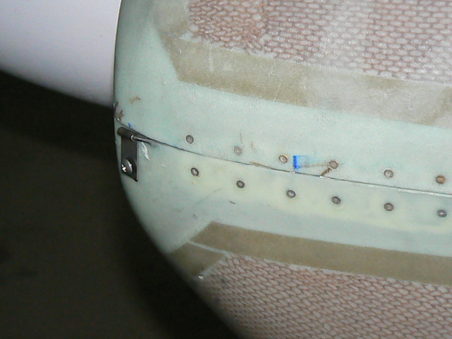
Fiberglass layup, with LOTS of sanding to be done. The black is a couple of layers of carbon fiber, as I suspect that I will try to hold on to this area when entering and exiting the aircraft.
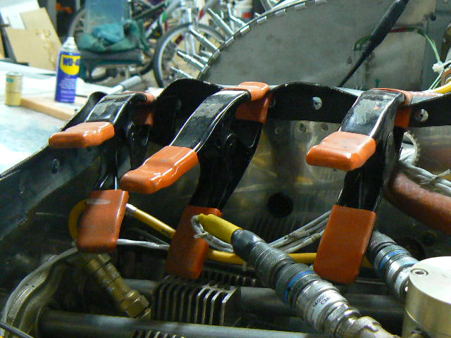
Attaching the baffle fabric. The clamps are an attempt to "train" this stip into bending forward.
The partially riveted baggage door is strapped in place to prepare for drilling the inner skin from the inside. Getting the drill, light, and my head and arms far enough underneath the panel is going to be interesting.
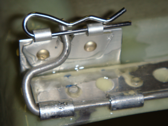
Ken Foote's solution for retaining the lower cowl hinge pins