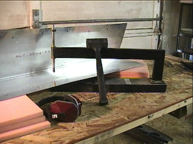
Preparing to drill the leading edge ribs to the spar. Lots of clamps to keep the rib from moving!
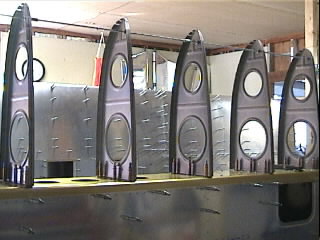
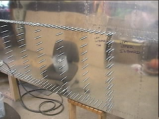
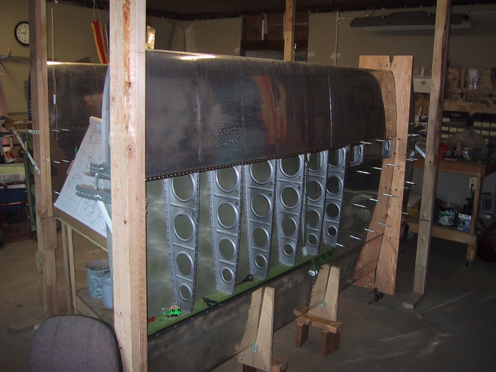
Left wing with leading edge and top skins drilled to the skeleton.
Building both wings together. Here, the right fuel tank ribs are being aligned in preparation for attaching the tank skin.
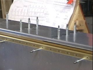
Drilling bottom skins onto the right wing. Note the three access holes just below the spar. The other opening is for the rear seat air vent.
Aligning the right wing leading edge ribs. Threaded rod and nuts on each side of each rib insure that the rib will not move as the skin is stretched over.
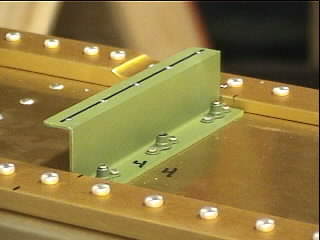
Z brackets hold attach to the back of the fuel tanks. The nutplates allow the tank to be bolted to the spar, so the entire fuel tank assembly can be removed.
Rear baffle of the right fuel tank. The Z brackets are underneath the baffle. In this photo, the baffle has just been drilled to the Z brackets.
Right fuel tank ribs are now drilled to the rear baffle.
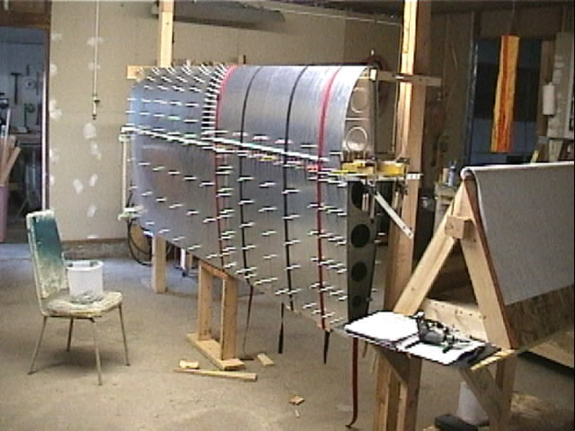
Drilling the left fuel tank skin to the ribs. Strap clamps hold the skin in place until drilling is complete and the assembly is held together with clecos.
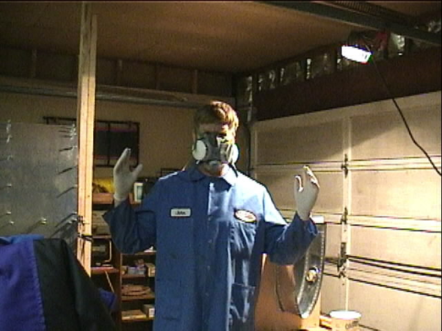
Gloved up and ready to Proseal!
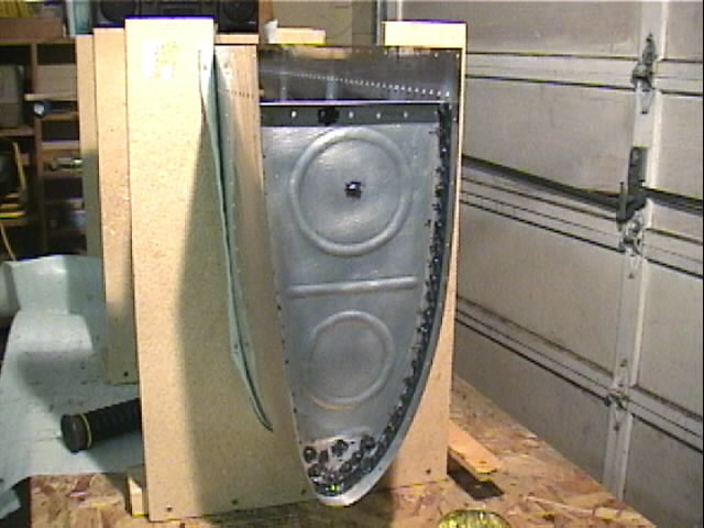
Fuel tank ribs have been riveted to the skin. ProSeal is used to seal the tanks. It is that lovely black stuff that decorates this photo.
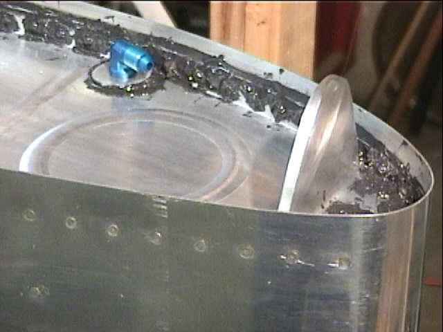
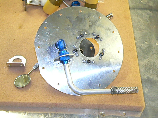
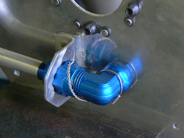
Closeup of the inboard rib of the right tank. The blue fitting is for the tank vent, and the substantial looking bracket on the right attaches the tank to the fuselage. Ain't ProSeal pretty?
While the ProSeal dries, might as well start the ailerons. The C-Frame tool is used to dimple the holes for the stiffeners.
Closeup of the dimple dies used to dimple a hole, seen in the foreground. You are looking at the inside of the aileron set into the C-Frame tool; the outside of the dimple allows a countersunk rivet to be used.
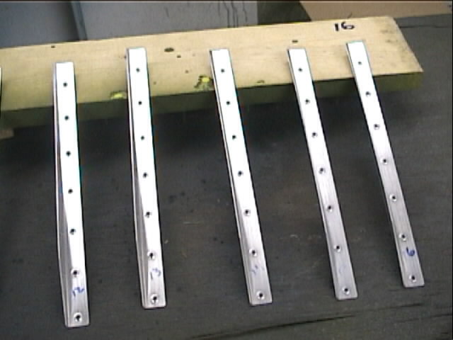
Stiffeners for an aileron, ready to prime.
Ready to prime the aileron skins and stiffeners.
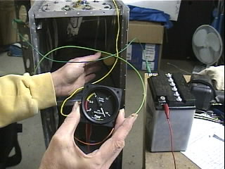
Diane testing the fuel senders and fuel guages. They work fine!
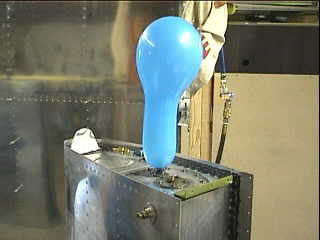
I cobbled together an air valve to leak test the tanks
A balloon acted as a safety net ... too much pressure would be a bad thing.
Sealing the filler hole was a challenge until Diane came up with the idea of stuffing a balloon into it.
Ready to rivet the left outboard topskin on!
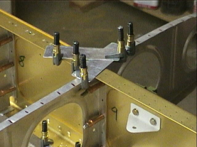
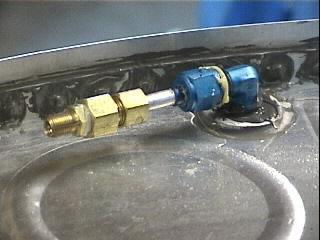
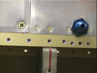
Detail of the pitot tube attachment. The main spar has been machine countersunk and the rib has been dimpled in prepartion for the bottom skin.
Aligning the aileron. You can barely see a string that I used as a plumb bob. When it aligned with the tooling holes, the aileron was properly "in trail".
Drilling in preparation for riveting rod end bearings onto aileron pusrods.
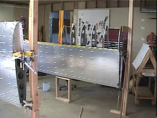
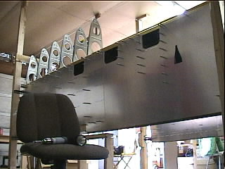
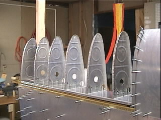
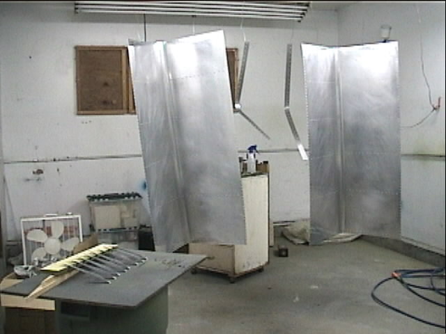
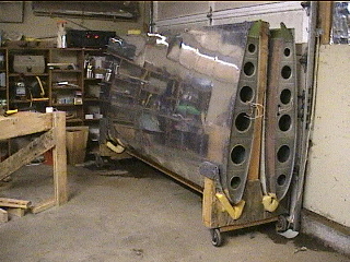
A Milestone!! Both (mostly) completed wings are in storage! Started in November, 1999, it took almost exactly 2 years to get them to this stage.
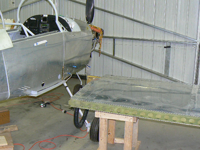
On to the Fuselage ... to be built on the jig being constructed on the left.
Drilling in preparation for riveting rod end bearings onto aileron pusrods.
Drilling in preparation for riveting rod end bearings onto aileron pusrods.
Drilling in preparation for riveting rod end bearings onto aileron pusrods.
As of February, 2007, the instrument panel wiring has been completed and tested. The next step is to hang the wings so I can test the fuel system prior to riveting the forward top fuselage skin on. But before the wings go on, I will implement Service Bulletin SB 06-2-23. The removal of the cover plates was not too difficult, but I had the advantage of the wings being not yet attached to the airplane. I elected to put all new parts in, so the cover plates, fuel pickups, bulkhead ells, and anti-rotation brackets are all new.
The service bulletin has you safety wire the nut attaching the fuel pickup to the ell. The anti-rotation bracket from Van's accomplishes this by design, but I figured that a little safety wire practice couldn't hurt. Prior to installing the cover plate assembly back on to the tank, pro-seal was applied around the bulkhead ell, the anti-rotation bracket, and over the rivets that attach the bracket and the platenuts for the cover plate.
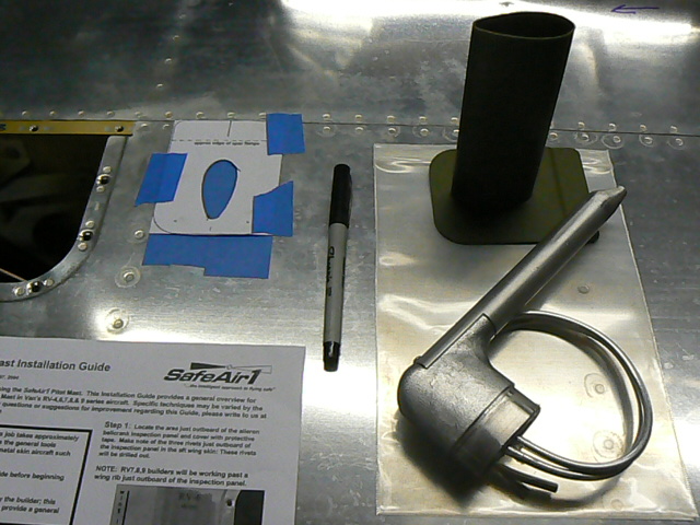
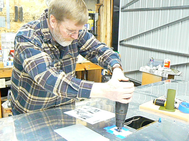
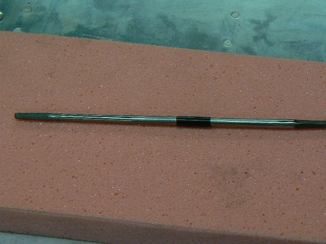
Preparing to install the mount for the Dynon Pitot Tube, which includes angle of attack.
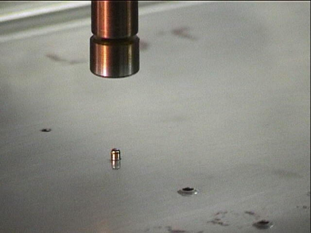
Using a step drill to start the cutout.
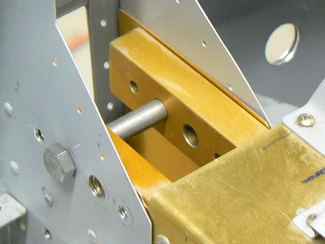
Using hardware store bolts to check alignment prior to attaching the wings. I had several problem areas here, all of them due to interference when the bolts tried to go through the landing gear weldment forward of the center section. It was clear that the close tolerance bolts that actually attach the wing would not go through without damage. After a discussion with Ken Scott at Van's I learned that it is permissable to open up the holes in the weldment, but that the holes in the spacers need to be left alone.
The holes in the upper portion of the weldment are accessable and were easily opened up with a carbide bit in a Dremel tool. But the holes on the bottom of the weldment are very difficult to get to. My solution was to fabricate a tool ... starting with a small round file, I ground away all but the tip. This allowed me to push the tool through each hole from the aft side and use the remaining file area to open up the weldment holes. The tape gave me depth information so I could avoid filing the spacers or hitting the forward parts of the weldment.
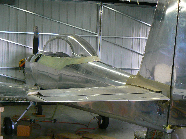
The right wing, staged and ready to attach.
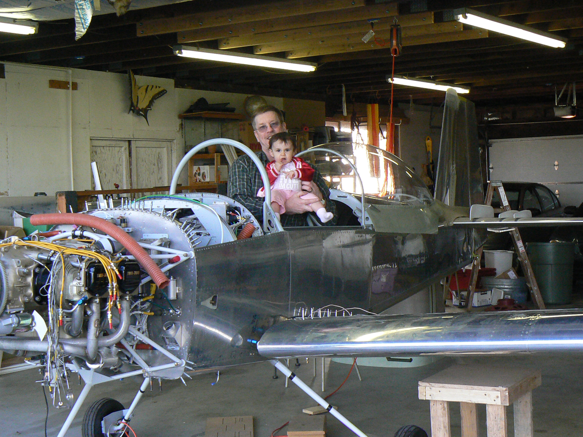
A happy builder with granddaughter after the wings slid home easily.
Son Kevin filmed the event, while Jim Clare (RV-4 builder and neighbor), Ken Foote, and Ray attached the wings. There is quite a bit of dihedral; with the tips help up quite high there was no problem getting the initial bolts in place.
Each wing is currently held in place with 2 hardware store bolts. The whole process took about 20 minutes, just like Jim suggested.