The design of the instrument panel has taken shape over a number of years and has gone in directions that I would not have predicted when I started this project almost 8 years ago. The availability of new instrumentation for experimental aircraft reminds me of the early days of home computers ... every month it seems that something new is available. I have tried to choose instruments with some history in the market place. The resulting panel is like nothing I have ever flown behind!
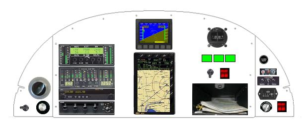
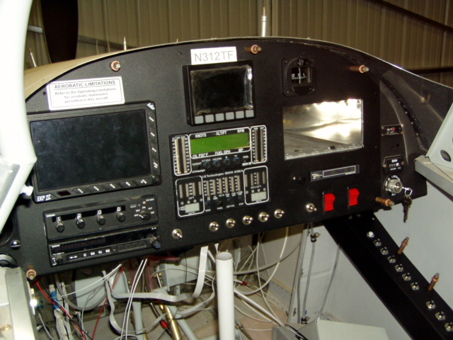
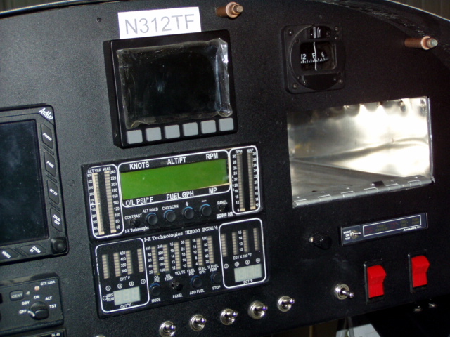
This is the panel plan as of 3/23/05. In the center is a Dynon D10A above an AvMap EKP-IV GPS. To the left is a Garmin GTX-320A transponder, an SL-40 comm, and an IK2000 engine monitor, selected for the quantity of information available at a glance and because it offers a direct interface to my FADEC engine. The green boxes on the right are where an annunciator panel for FADEC will be located, just below a mag compass from Van's. Switches to control FADEC are located above Van's map box. The left sub-panel holds the flap switch, trim knob, and fresh air vent. On the right sub-panel are the key switch, the ALT and BAT switches, Hobbs meter, intercom, ELT remote panel, and the heater control.
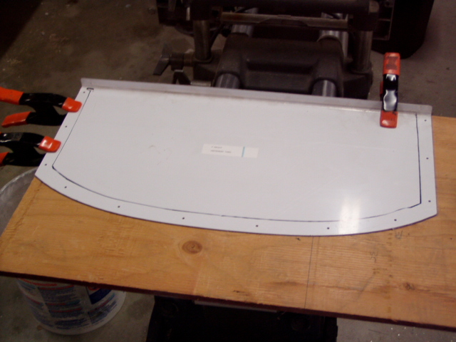
The plan is to rough the panel in with plywood to prove the fit and location before committing to aluminum.
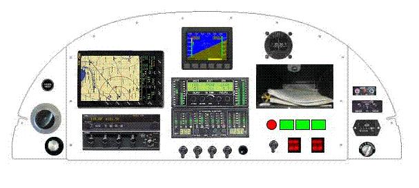
This is the panel plan as of 5/20/05. No instruments have changed, but the location of several needed to be modified. The botom of the map box must be between 3.5 and 4.75 inches above the bottom of the panel, so it clearly needed to be moved. I also did not feel that the first plan left enough room to effectively mount the GPS or for panel mounted switches. It took 3 or 4 iterations of the layout plan to come up with this one. As of 5/20, the side panels have the instruments mounted and lines are being drawn on the main panel in preparation for cutting the holes.
Many thanks go to Bill VonDane for his Experimental Panel Builder, which allowed lots of "what if" panel experiments to be run in a very short time. Try it out here.
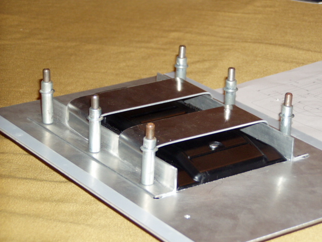
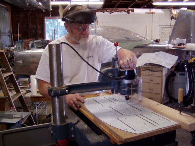
We are cutting the holes in the panels with an overarm pin router. The resulting holes require hand filing, but if the corners of the rectangles are accurately placed by carefully drilled holes matching the diameter of the cutting tool in use, I am happy with the outcome. Besides, I rarely get to use this tool ...
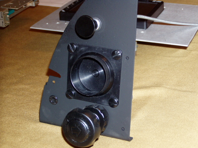
The left sub-panel. I moved the flap switch to the main panel and put the heater control here.
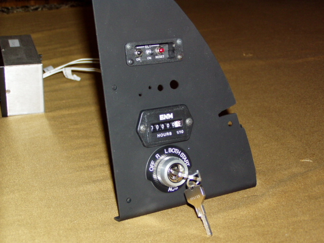
The right sub-panel. The holes above the Hobbs will hold the intercom.
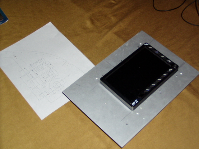
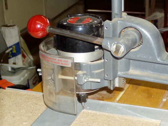
And, plans can change. I have been cutting sample holes using an overarm pin router (see picture below), and intend to cut the holes in the panels when I am comfortable with the technique. Here, the GPS sits in a test cutting.
The backside of the GPS hole, showing how I intend to mount it. The unit will slide in from the front of the panel and heavy-duty Velco will secure it.
After taking 47 deep breaths and the odd Valium or two, the first holes in the main panel get cut.
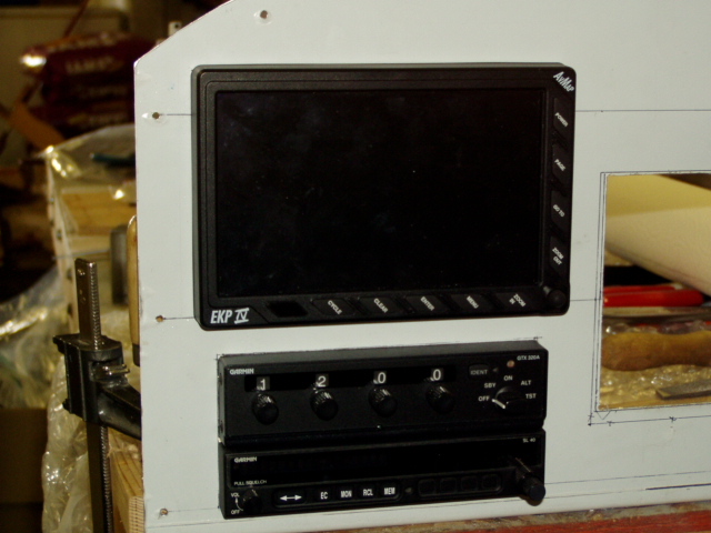
First fitting of the GPS, transponder and radio.
There are two odd things in this picture ...
Prior to wiring up the panel ... first test fit.
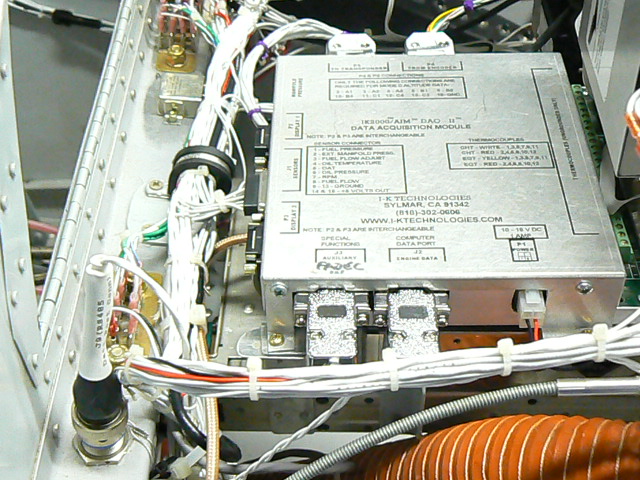
Centerpieces are a Dydon D10A and the IK2000 engine monitor.
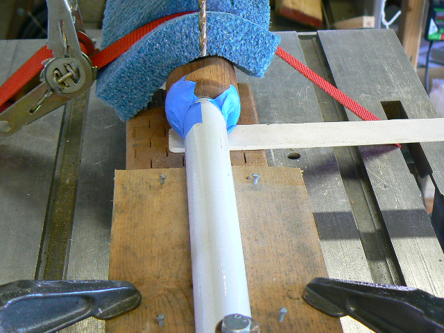
Ready to drill the forward stick for a pin to hold the wooden grip in place.
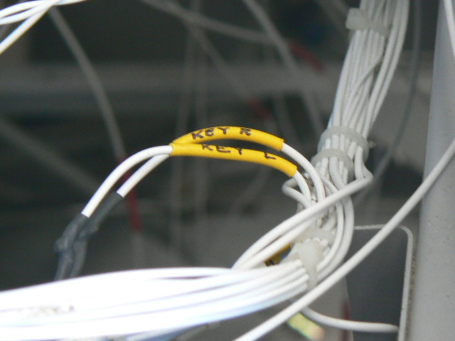
We are using an inexpensive labeling technique ... colored shrink tubing and a fine-tip Sharpie. We tend to route the wires and tie-wrap to the growing bundle as we go. As a section gets completed, we cut the tie-wraps and re-install them around the completed bundle. This one is in progress ...
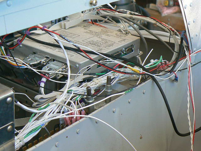
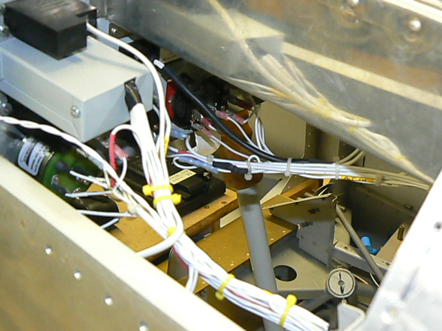
Looking through the access panel from the forward baggage box at the wiring in progress. The control unit for the IK2000 Engine monitor sits on top of the radio and transponder.
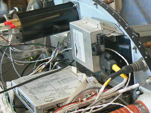
Oriented vertically above the IK control box is the FADEC Health Status Annunciator, which is mounted immediately behind the homemade mount for the Avmap EKP-IV GPS. The Dynon D10 has plenty of room in the center of the panel.
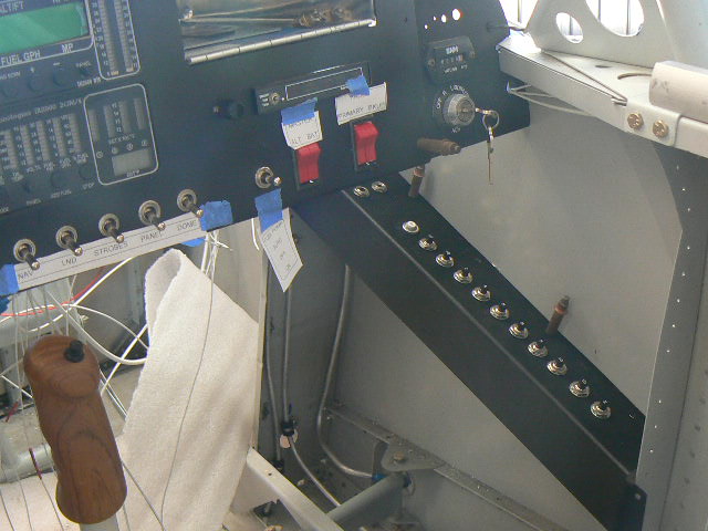
A view from the inside, where the stick grip is mounted and the breaker panel is ready to wire.
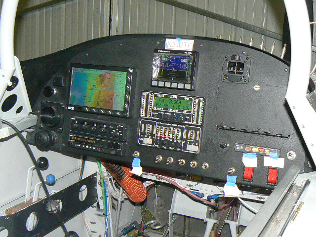
The Panel wiring is completed, except for running wires out to the wing tips for lights and strobes.
Bundles handling switches, intercom and ELT. The plan now is to hang the wings, complete the wiring, and hook up the fuel lines so that the fuel pump can be tested. I want to make sure there are no leaks in the in-cabin fuel system before riveting the topskin on.
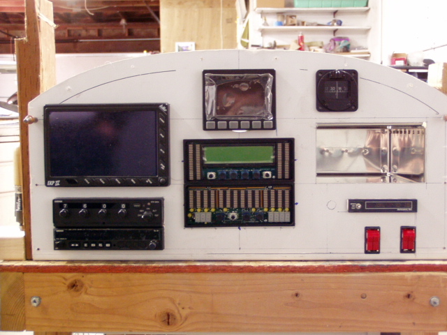
The completed panel all lit up. It looks better when you are sitting in the airplane ...